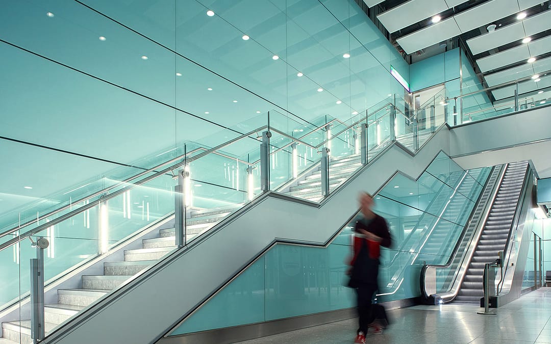
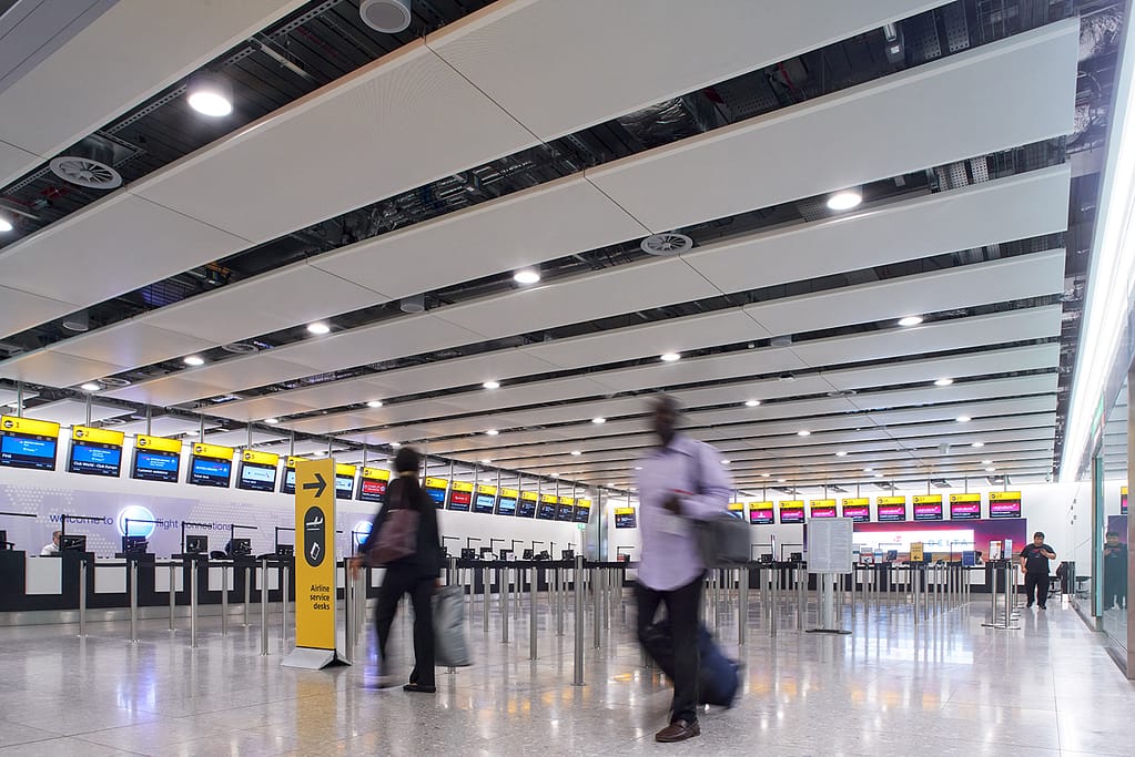
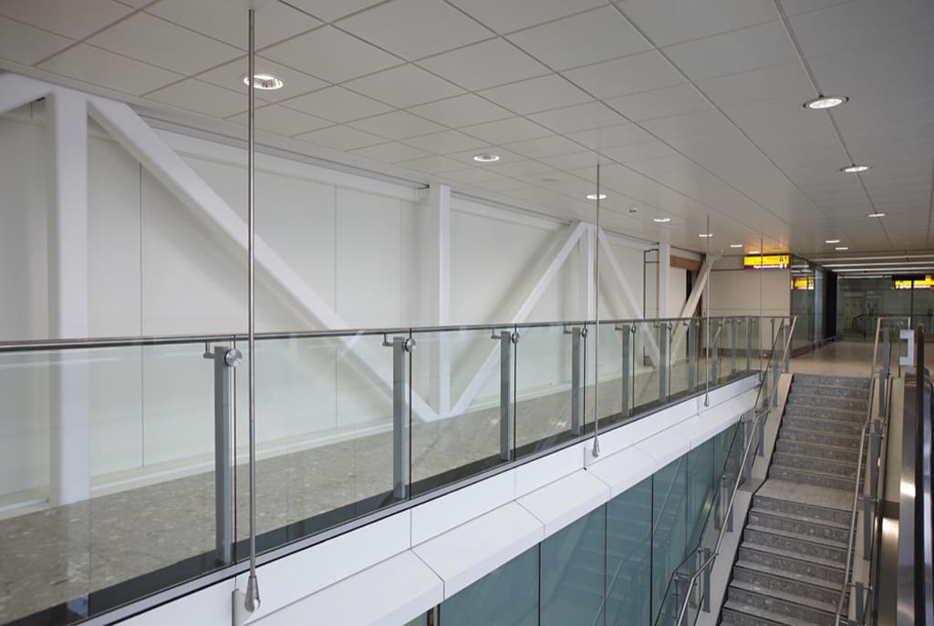
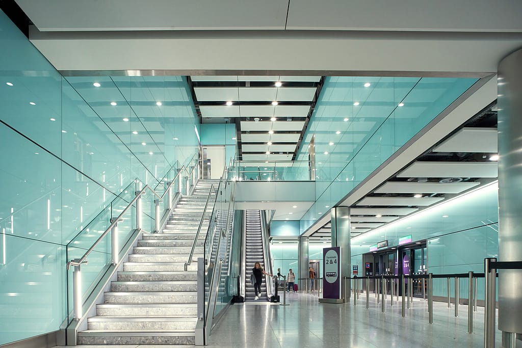
There are few places where your work will be viewed by tens of thousands on a day to day basis. Heathrow airport is one of those places. It was my absolute pleasure to be involved with this project.
During the revitalisation of T3 I was tasked with the production drawings for the Stair Structure and Glass Balustrade Systems. As well as the various support structures throughout the project. We were to incorporate the original 2-D parts details as utilised in T2 into the new details, so that the continuity of design would flow from one terminal to the next.
Whilst the part details would remain, there was still a lot of design required around the interfaces of existing elements such as the hanging supports for the retail sector which needed to fit around existing HVAC and main structure. The new stair structures and balustrades which needed to interface with the new escalators. Not to mention the glass partitions and monitor displays that were fitted to cambered beams, requiring adaptive mounts.
Overall this was a challenging project with a rewarding outcome.
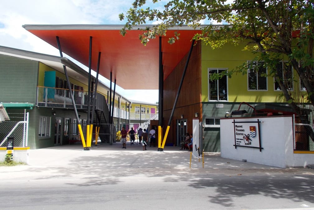
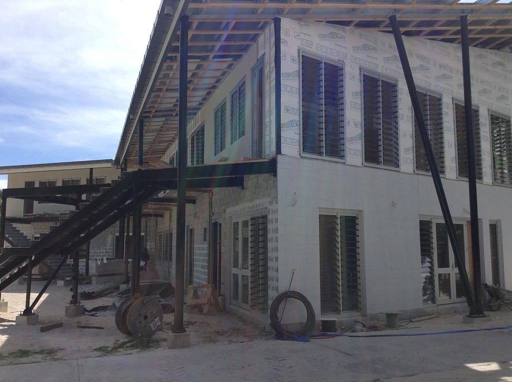
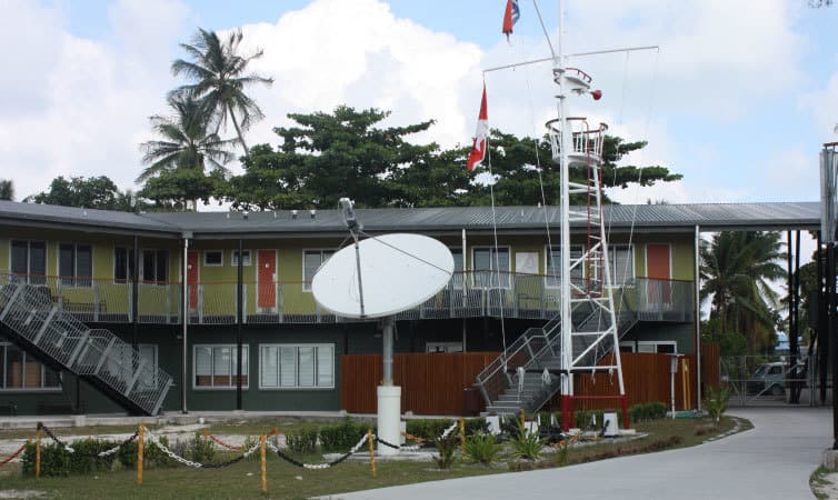
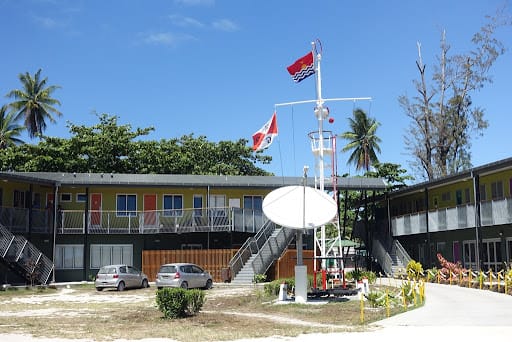
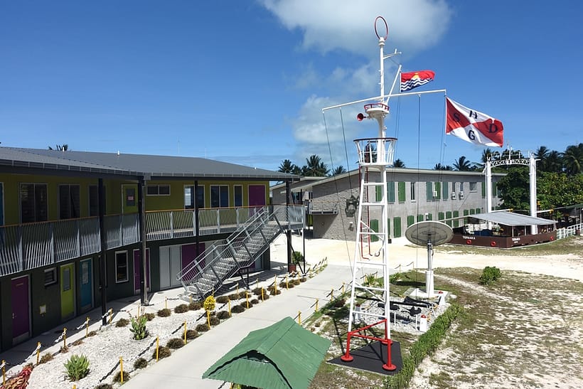
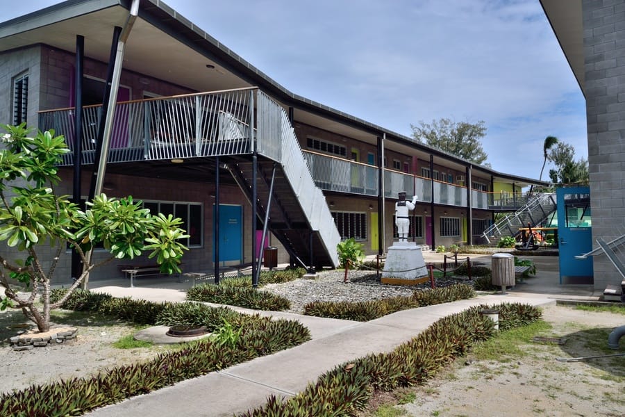
Location: Kiribati, Gilbert Islands, Pacific Ocean (circa. 2006) Design Brief: New Build Structure, Walkways, Stairs and Balustrades CAD System: StruCad
Quite often we are presented with projects on tight deadlines. This can be due to a variety of reasons, but how often is it because there is only one boat leaving and the next might not be for another three months or so?
This is how this project began with a two week turnaround for the metalworks and structure design package to be completed, including review and approval. It was with these criteria that I was presented and asked, ‘can we make it happen?’ The answer was, ‘yeah, but it’s gonna be tight!’.
So. No time to spare. Impossibly large package of work to complete. What could go wrong? The answer to that is, nothing. Nothing could go wrong, there was no room for that either.
My plan was to model the main structural components to form a project basis and split the work packages into two areas. Main Structure and everything else.
I got to work and completely modelled the structure without connections. This allowed us to have an accurate layout. Then I shared the model with my colleague where he continued with the structural connections and I continued with the walkways, stairs and balustrade details.
It was with this strategy that we were able to complete our design in time as well as having a fully coordinated package, all of this before multiuser space really took off.
I’ve found that when we are confronted with problems there is an opportunity to think outside the box to find solutions. It’s the mindset that helps drive a solutions based approach to my work.
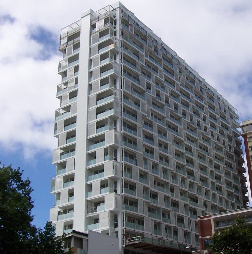
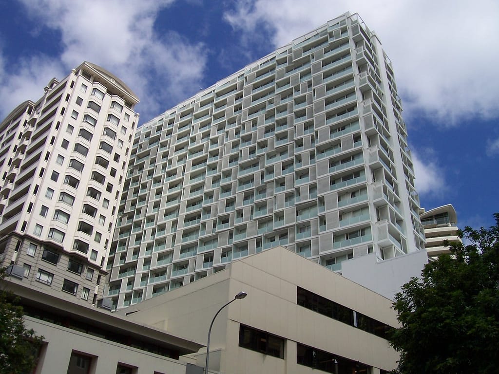
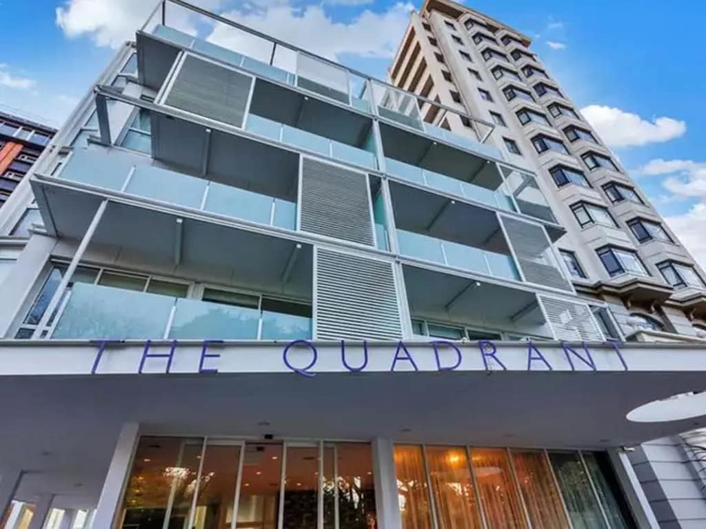
Location: 10 Waterloo Quadrant, Auckland CBD, New Zealand (circa. 2005)
Design Brief: 23 story building comprising over 250 hotel apartments
CAD System: StruCad
My role as the main design draughtsman was to detail the structural steel elements within our project scope. This comprised the balcony support system, the two fire escape stair cores and the roof structures; all according to the architect’s design and engineer’s specifications and has been the largest project I had been given responsibility of delivering up to that point in my career.
Each floor had a unique balcony arrangement and on those balconies each one had a structural support system for the balcony above, whilst also housing the sliding sun shades for the floor below.
The main challenge for me was the balcony supports. As each floor was different I needed to come up with a method of approach when modelling the structural support so that I wouldn’t need to go through and model every connection individually. With the sheer number of connections the solution needed to cut this drawing time to an absolute minimum.
In the end I took the advice of my senior colleague and took the time to write a parametric connection based on the angular input of each member. Dedicating the time at the beginning of the project paid dividends with a greatly reduced modelling time overall.
A major issue was the inclination of the roof plane on the end retail space. The space of the building was angular and the way the architect had indicated the falls and eaves lines would have meant that the roof would’ve had a twist through it.
After some discussion we determined the architect hadn’t intended this design discrepancy and so I was able to model the roof in a single pitch and demonstrate the new roof intersection lines. This reconciled the angular nature of the roof design and was a wonderful way of demonstrating the advantages of 3-D modelling.
Since then I’m pleased to see more have taken up modelled structures to improve the visualisation of their concepts.
The variety of complexity within the job and problem solving through the issues was enjoyable and a great learning experience of a project well done.
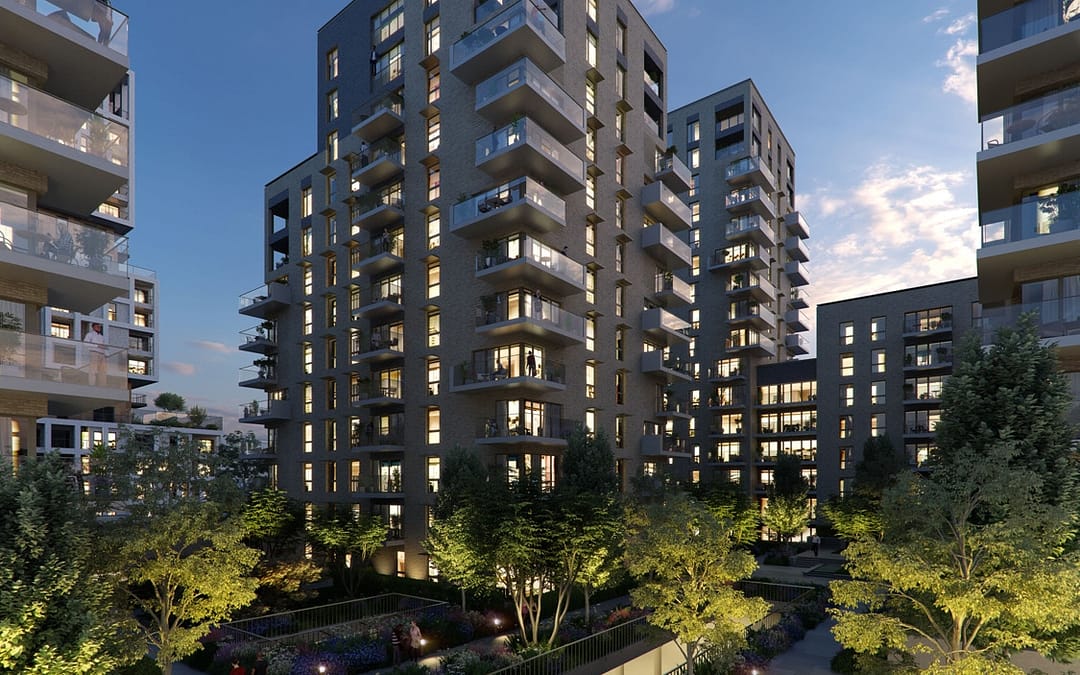
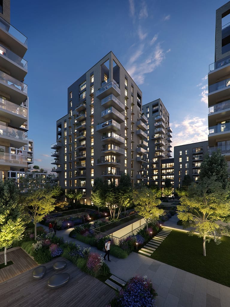
Location: Kidbrooke, London (circa. 2019) Design Brief: Phase 3 / Block D Metalwork Package CAD System: AutoCad Advance Steel
Kidbrooke is part of a broader residential redevelopment strategy undertaken by Berkeley Construction in South East London. For the Third Phase Block D section of this project I was tasked as the lead metalwork designer and with further design coordination.
The redevelopment comprised five main residential buildings of varying height which share a communal green space on a raised podium. At street level there are a number of generous retail spaces.
My role was to fully expand design on the balustrades at the podium level (metal and glass); the main entrances to apartment blocks; retail space canopies; car park and BoH metalworks including the automated gates as well as any other miscellaneous metal works that could fall under our scope of works as the project progressed. Simultaneously ensuring the design was harmonious within this project and previous phases.
The Substation doors were easily one of the biggest design challenges. The subcontractor responsible for substation louvre doors wasn’t able to manufacture the doors or the system because it was just too big, the structure was way outside the scope of what any louvre company could provide.
The door needed to be robust and secure (SR2), but like any other substation it needed to facilitate removal of the UKPN transformers for maintenance. To solve this issue I proposed incorporating a hybrid approach.
The main structure would be adapted to normally be bolt fixed in it’s closed position with louvre panels set into the frame work. During maintenance they could unbolt the doors around the perimeter and they would swing open through 180 degrees to allow unimpeded access to the substation.
By incorporating hidden proprietary hinges arranged in a unique way, meant that all areas were able to meet strict ‘secure by design’ criteria whilst also meeting the UKPN maintenance requirements. A clear win for everyone.
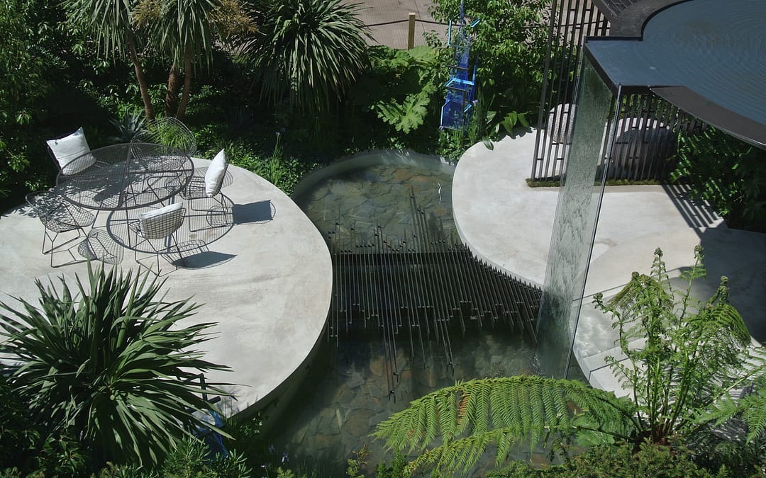
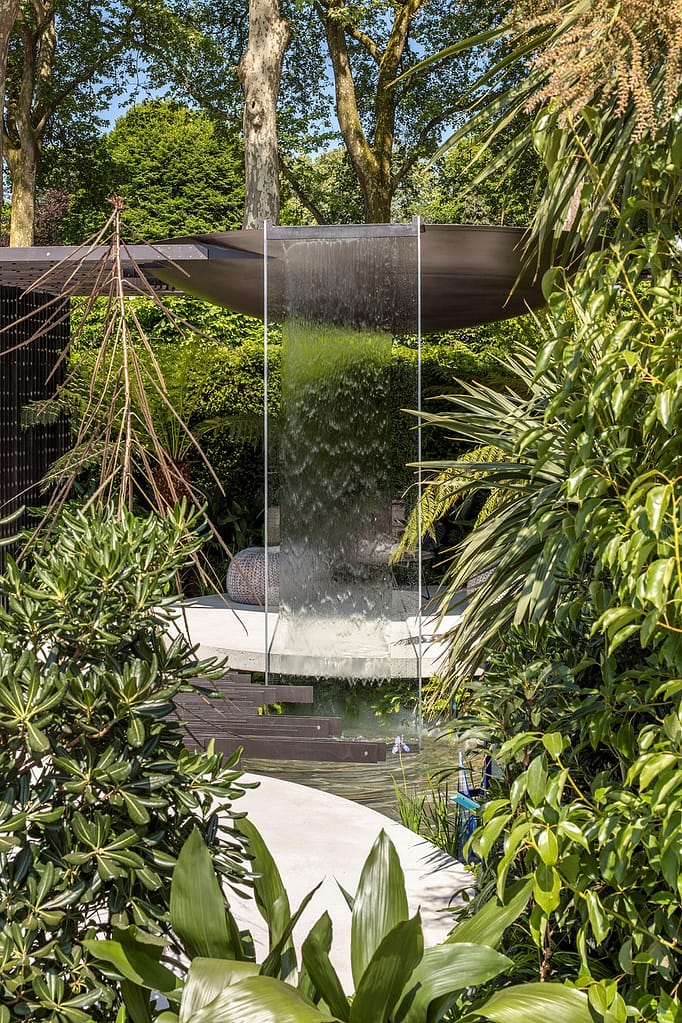
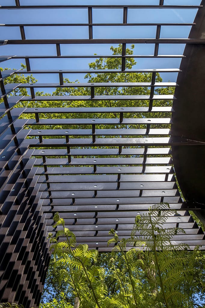
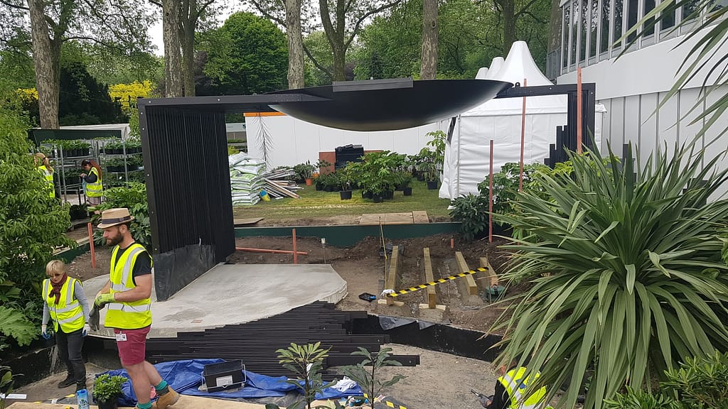
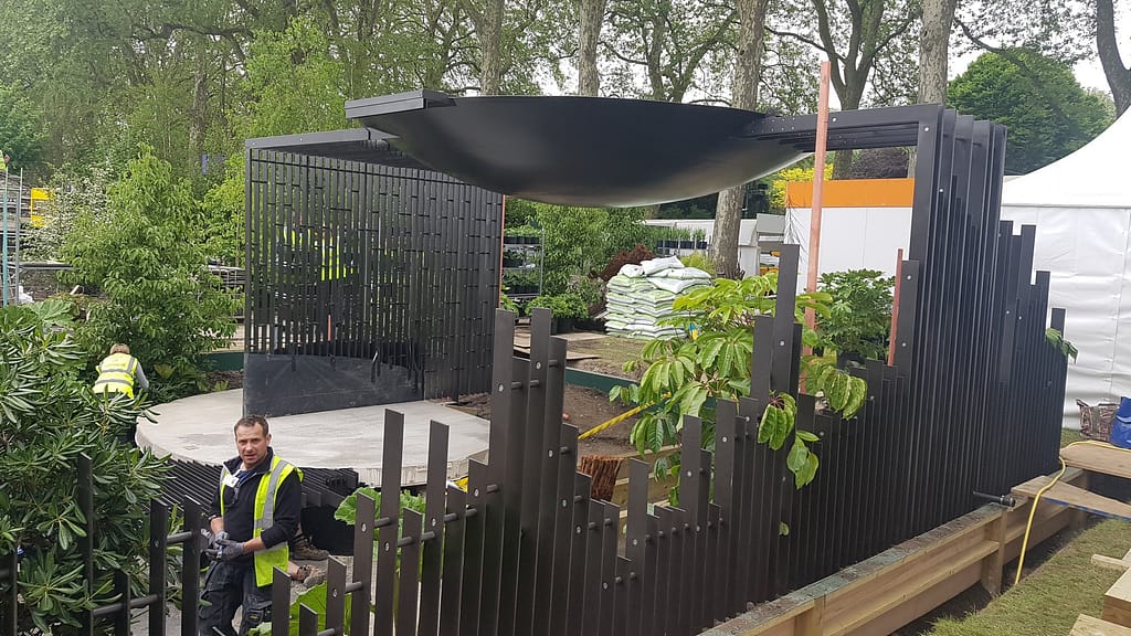
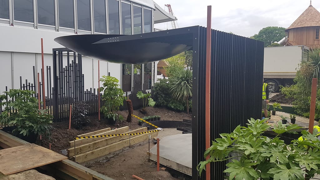
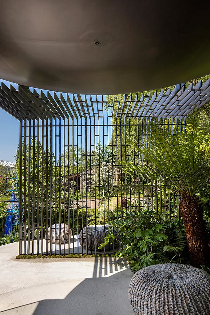
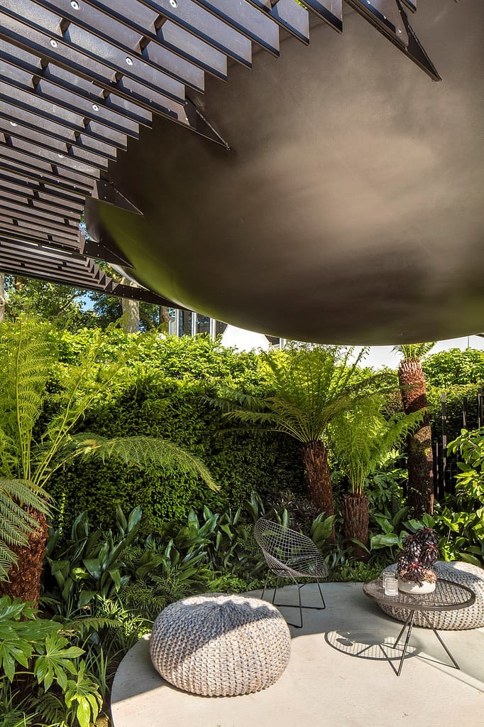
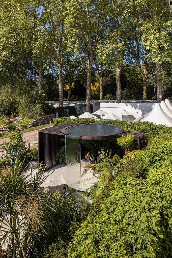
Location: Chelsea Flower Show, London (circa. 2018) Design Brief: Spirit of Cornwall Exhibition CAD System: AutoCad Advance Steel
I was presented with a unique opportunity to be sole designer of the metalworks for the Spirit of Cornwall exhibit at the 2017 Chelsea Flower Show.
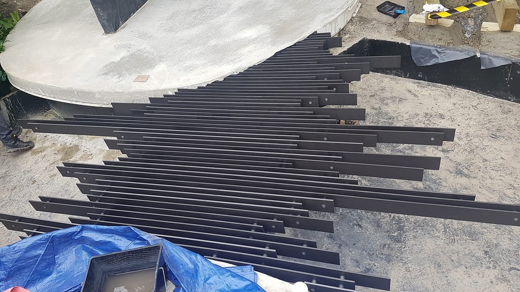
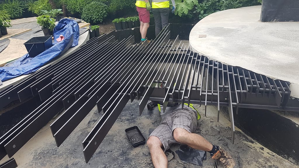
The main structure was supported by a flat bar lattice frame on either side, together with walkway sections and fence panels, of the same theme.
The way that it had been visually designed by the architect, whatever fixing methods we used needed to be flush and near invisible to the eye. We couldn’t have any protruding bolt heads or threads which presented a challenge of how it should all be bolted together. Not only that, the exhibit needed to be deconstructed into multiple sections.
The solution was that the spacer tubes that run between the flat bar structure should be internally threaded and we would use a combination of countersunk bolts and threaded studs.
By strategically placing the tube spacers, we were able to form a structure that was demountable and moved to its permanent home in Cornwall after the show had ended.
During fabrication, the dish itself had to be spun by a specialist metalworks company, and when we received it, at first measure, it appeared to be within specs. But once the fabricator started putting all the pieces together things just weren’t matching up.
With the fabricator at a loss for what was wrong I had to go out into the workshop and figure out what was going on for myself. As it turned out that although the overall diameter of the dome was correct they had actually spun it to the wrong radius this meant that it was about 100mm too deep at the apex.
After some recalculating we came up with a method for joining all that back together without compromising the overall scheme of the dome piece.
There were a couple of interesting features incorporated into the design. The outlet for the waterfall needed to be precisely level, so I designed a tilting outlet.
Once the structure was installed and water was introduced into the feature whoever was installing had the ability to fine tune the water pour without needing to re-level the entire structure.
There was also the fear of the waterproofing of the feature leaking inside the dome. With all the shifting around it was a real concern.
We had to have a lifting eye in the centre of the dome whilst at the workshop to be able to lift and manoeuvre the structure during fabrication. My suggestion was to permanently weld the nut on the inside of the dome and to make a removable plug that could be periodically removed incase of water ingress.
Both are simple solutions that make a difference to the end product installation and future maintenance.
We use cookies on our website to give you the most relevant experience by remembering your preferences and repeat visits. By clicking “Accept All”, you consent to the use of ALL the cookies. However, you may visit "Cookie Settings" to provide a controlled consent.
This website uses cookies to improve your experience while you navigate through the website. Out of these, the cookies that are categorized as necessary are stored on your browser as they are essential for the working of basic functionalities of the website. We also use third-party cookies that help us analyze and understand how you use this website. These cookies will be stored in your browser only with your consent. You also have the option to opt-out of these cookies. But opting out of some of these cookies may affect your browsing experience.
Necessary cookies are absolutely essential for the website to function properly. These cookies ensure basic functionalities and security features of the website, anonymously.
Cookie
Duration
Description
cookielawinfo-checkbox-analytics
11 months
This cookie is set by GDPR Cookie Consent plugin. The cookie is used to store the user consent for the cookies in the category "Analytics".
cookielawinfo-checkbox-functional
11 months
The cookie is set by GDPR cookie consent to record the user consent for the cookies in the category "Functional".
cookielawinfo-checkbox-necessary
11 months
This cookie is set by GDPR Cookie Consent plugin. The cookies is used to store the user consent for the cookies in the category "Necessary".
cookielawinfo-checkbox-others
11 months
This cookie is set by GDPR Cookie Consent plugin. The cookie is used to store the user consent for the cookies in the category "Other.
cookielawinfo-checkbox-performance
11 months
This cookie is set by GDPR Cookie Consent plugin. The cookie is used to store the user consent for the cookies in the category "Performance".
viewed_cookie_policy
11 months
The cookie is set by the GDPR Cookie Consent plugin and is used to store whether or not user has consented to the use of cookies. It does not store any personal data.
Functional cookies help to perform certain functionalities like sharing the content of the website on social media platforms, collect feedbacks, and other third-party features.
Performance cookies are used to understand and analyze the key performance indexes of the website which helps in delivering a better user experience for the visitors.
Analytical cookies are used to understand how visitors interact with the website. These cookies help provide information on metrics the number of visitors, bounce rate, traffic source, etc.
Advertisement cookies are used to provide visitors with relevant ads and marketing campaigns. These cookies track visitors across websites and collect information to provide customized ads.