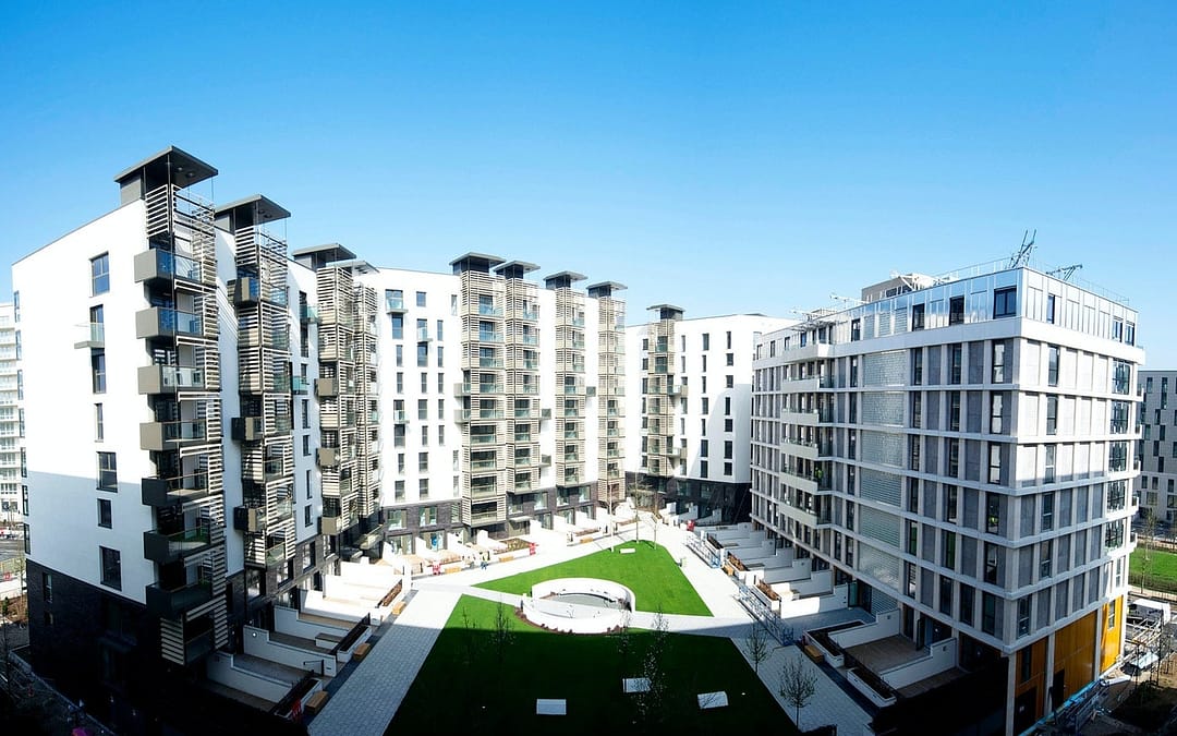
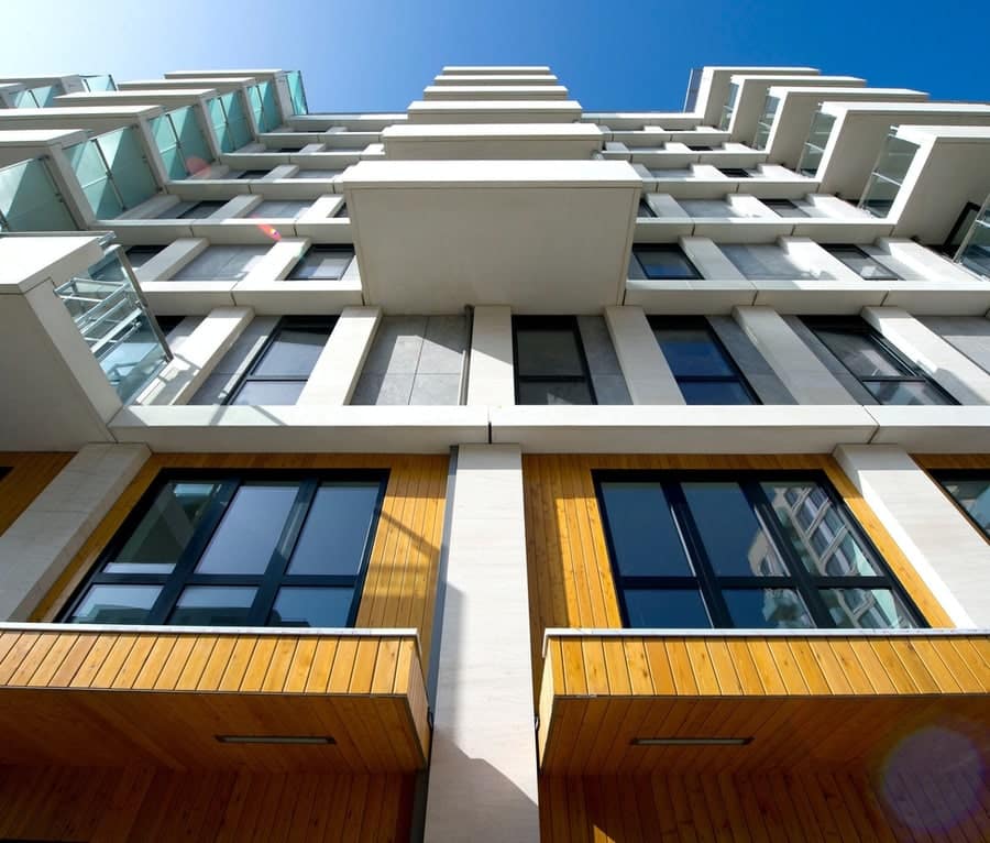
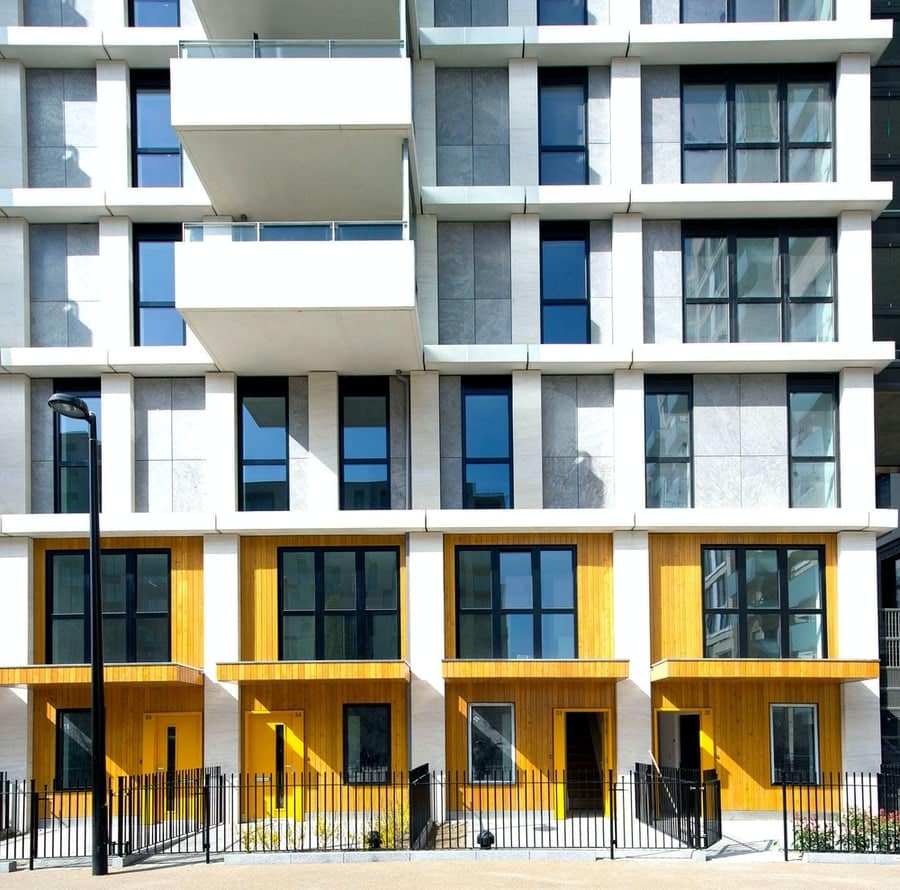
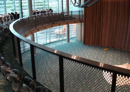
Design Brief: Balustrades and Wintergarden Structure Design
CAD System: AutoCad
I had the pleasure of working with the design team on what would be the Athletes Village for the 2012 Olympics in London that would later become residential housing.
Photo Credit: Haworth Tompkins
A project that consisted of structural privacy screens and balcony balustrades, stair balustrades, rails, and a winter garden joining two adjacent blocks.
The winter garden structure was particularly interesting since the engineer had specific ideas around section use, and the fabricator chosen had limited experience with heavy sections. I was able to offer my expertise with heavy steel as this was the basis of my trade certification.
Photo Credit: Haworth Tompkins
Through the strategic application of heat and cutting methods I was able to demonstrate that it is entirely possible to cut down sections without warping or massive postprocessing treatment.
Having a strong practical grasp of heavy engineering meant that I was able to resolve and help complete this project to exactly what the engineer had envisioned.
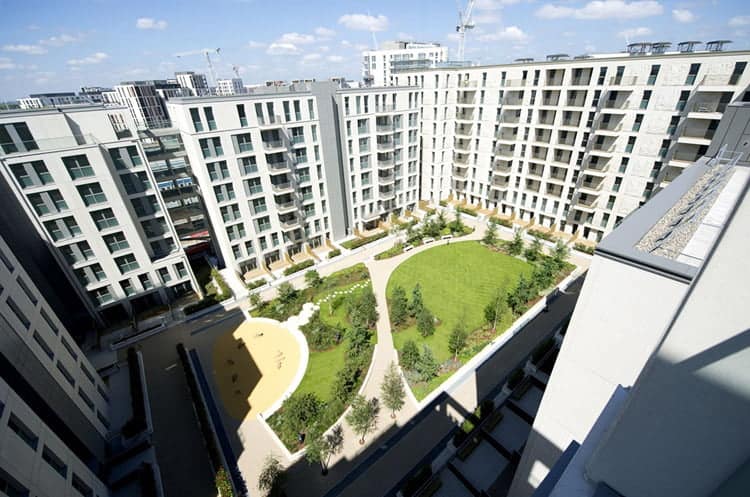
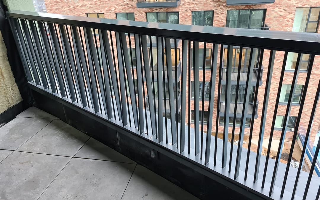
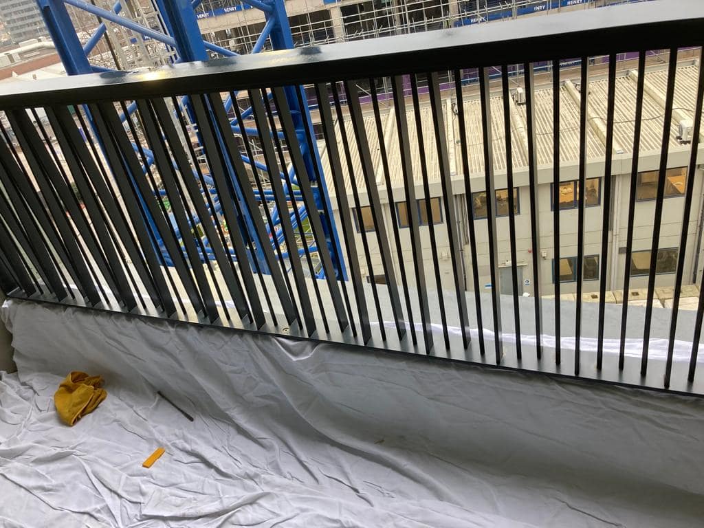
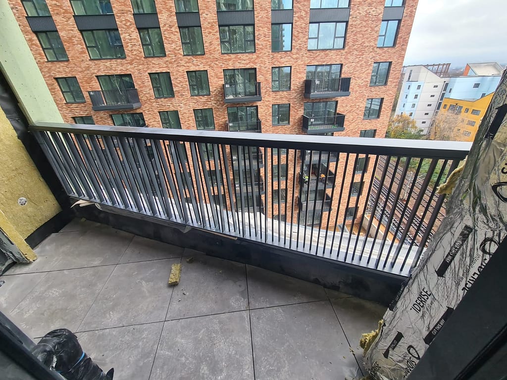
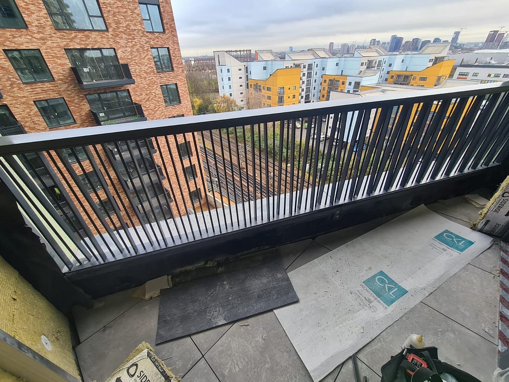
Design Brief: Balustrades – Block D comprised of 26 Stories & Block B comprised of 14 Stories
CAD System: AutoCad Advance Steel
Mid 2021 I was presented with a project in East London that covered 2 new residential tower blocks. One 14 stories tall, and the other, a commanding 26 stories. The brief was fairly straightforward – come up with a system that could make the fabrication and installation as efficient as possible whilst maintaining the architect’s design aesthetic.
This reminded me of a project I had worked on many years earlier while still in New Zealand. The infill bars weren’t completely welded, instead they were drilled and captivated within the outer frame. The only issue here was that we weren’t using a round bar or tube, we were using flat bars.
The result was a plasma cut top and bottom rail with just enough clearance to allow the flat bar infills to be inserted and welded from behind. Welding distortion and grinding were kept to a minimum which really helped to speed production.
The other issue was installation: how do you account for early production while still ensuring the balustrades are going to fit? The answer was a unique first fix bracket system that once installed would make allowance of up to 25mm of variance in the concrete structure.
By also making these universal I was able to reduce fabrication set up as well as logistics. If the site teams don’t have to find a particular bracket then they really only need to make sure they have the right quantities delivered at any given time.
So it was with this idea that I was able to help deliver 830m of complete design balustrades in a matter of weeks rather than the originally anticipated months.
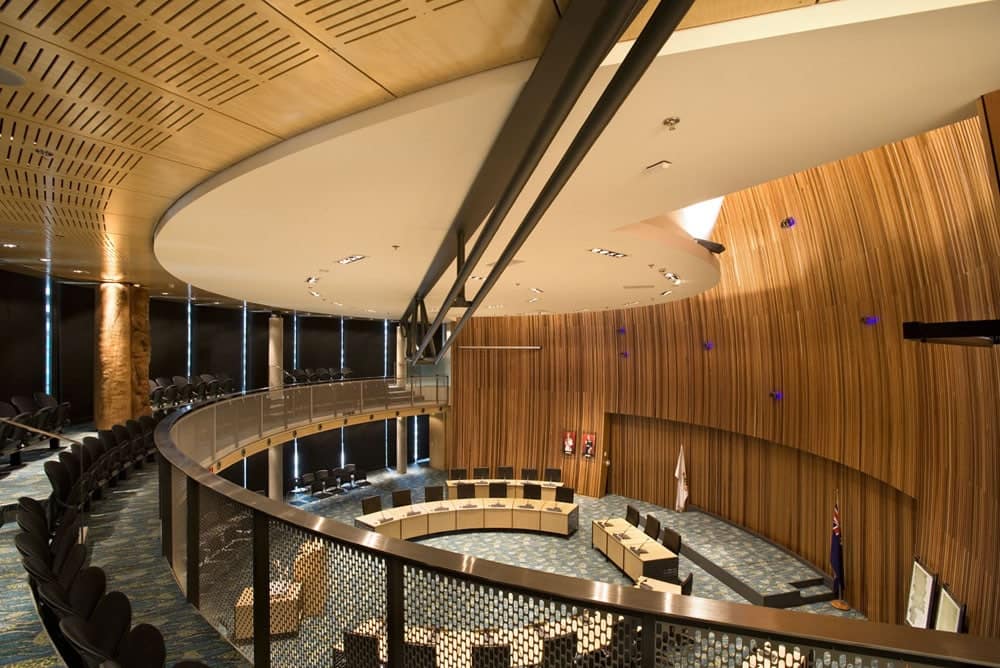
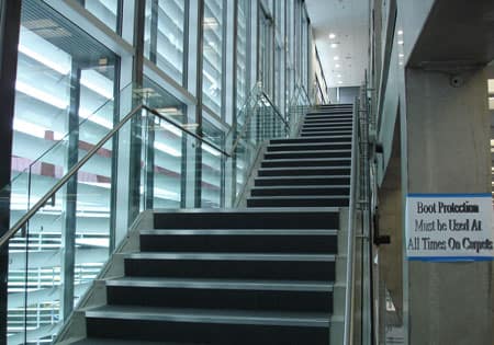
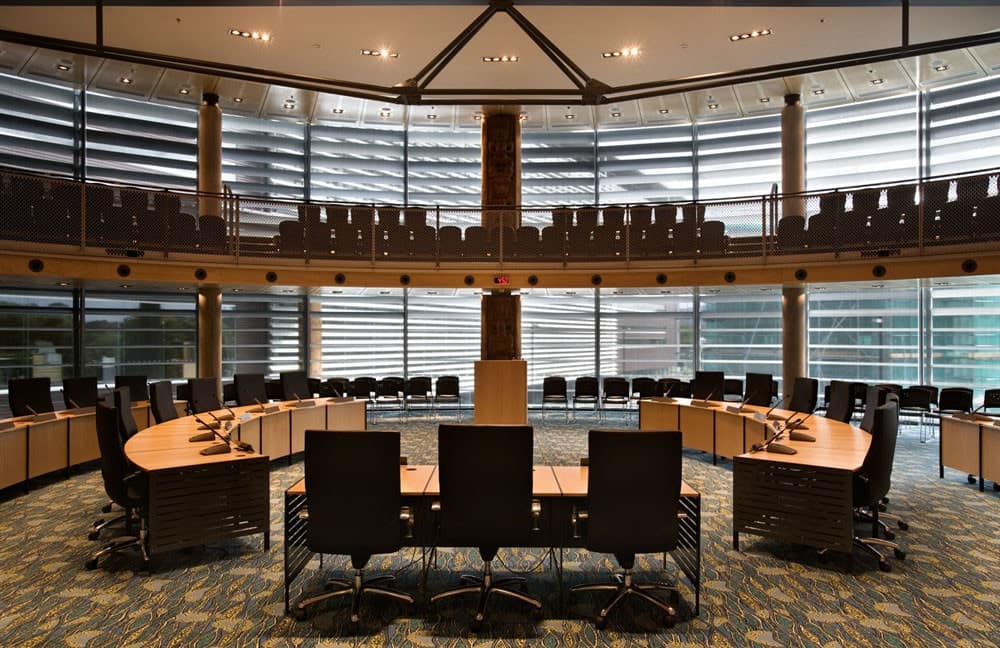
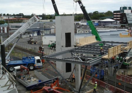
Design Brief: New Council Building Metalworks Package and Temporary Works
CAD System: StruCad
I had the opportunity to work on the handrails and balustrades scattered around what was to be the new Civic Centre for Waitakere City. An audacious concept for a public building it would also become the transport hub for the wider city.
Photo Credit: Arch Daily
One particular feature I enjoyed was the Link Bridge across the main TransRail tracks. This required a temporary works form to straddle the rail tracks so that the reinforced concrete could be placed and poured without disruption to rail traffic.
With millimetre precision and a 4 hour time slot the site team were able to install the framework without incident.
Although destined to be removed I was always proud of the structure designed for a quick installation without fuss.
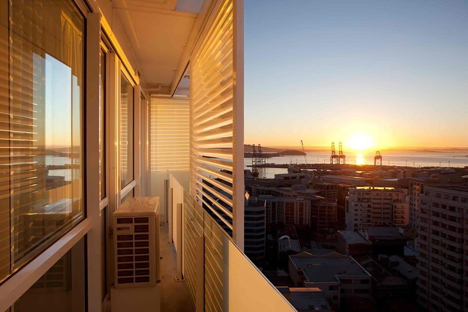
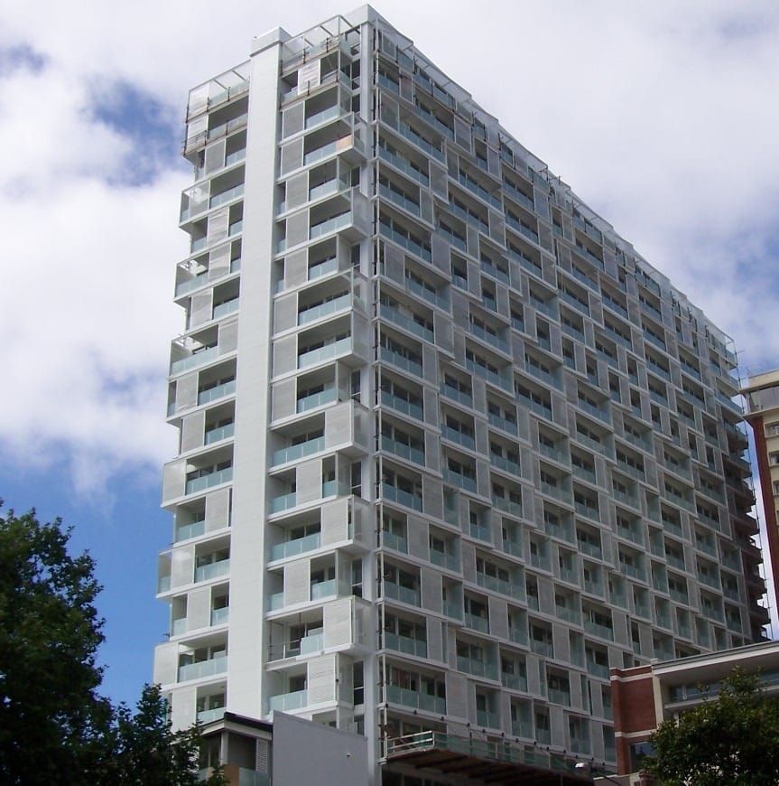
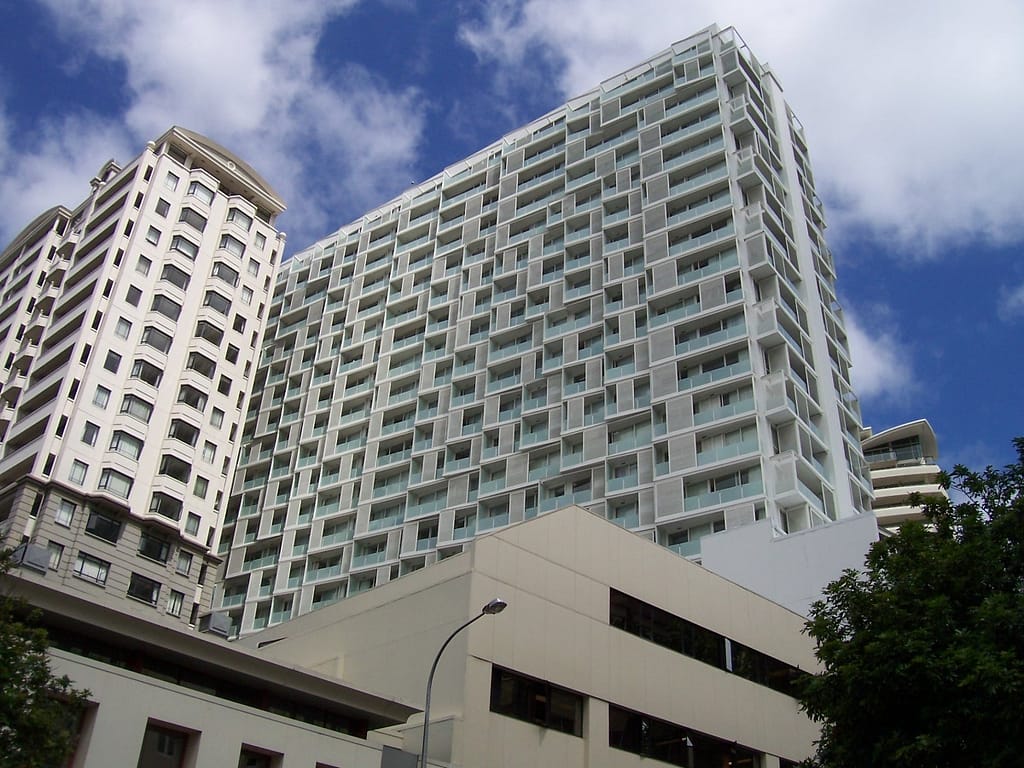
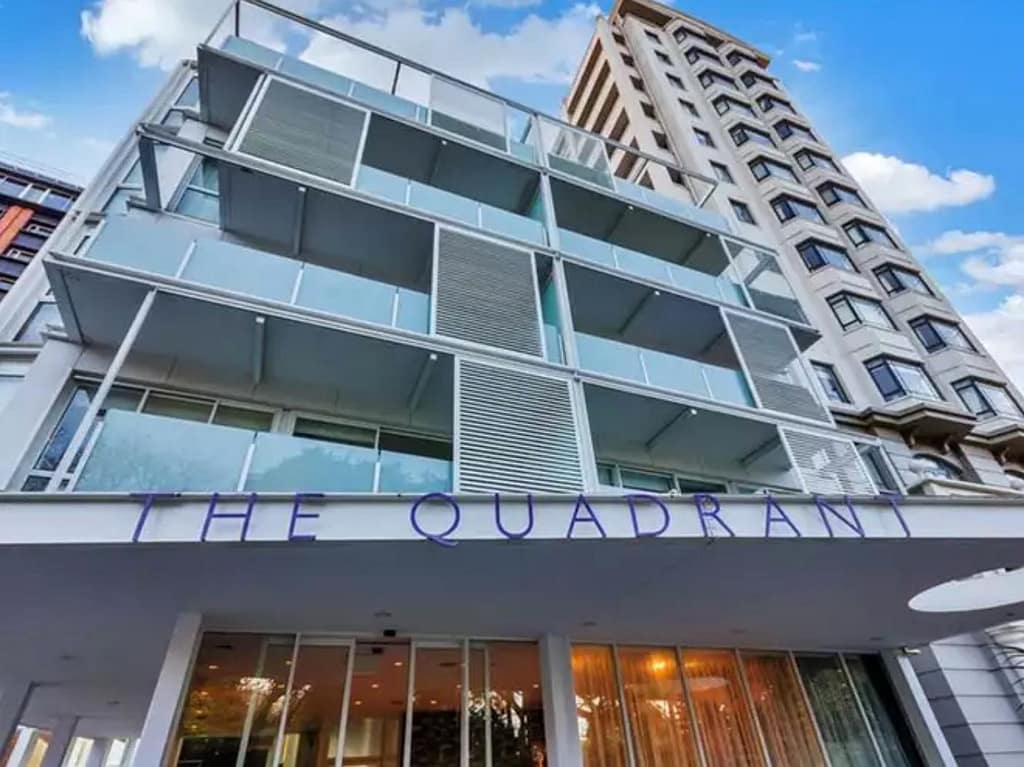
Location: 10 Waterloo Quadrant, Auckland CBD, New Zealand (circa. 2005)
Design Brief: 23 story building comprising over 250 hotel apartments
CAD System: StruCad
My role as the main design draughtsman was to detail the structural steel elements within our project scope. This comprised the balcony support system, the two fire escape stair cores and the roof structures; all according to the architect’s design and engineer’s specifications and has been the largest project I had been given responsibility of delivering up to that point in my career.
Each floor had a unique balcony arrangement and on those balconies each one had a structural support system for the balcony above, whilst also housing the sliding sun shades for the floor below.
The main challenge for me was the balcony supports. As each floor was different I needed to come up with a method of approach when modelling the structural support so that I wouldn’t need to go through and model every connection individually. With the sheer number of connections the solution needed to cut this drawing time to an absolute minimum.
In the end I took the advice of my senior colleague and took the time to write a parametric connection based on the angular input of each member. Dedicating the time at the beginning of the project paid dividends with a greatly reduced modelling time overall.
A major issue was the inclination of the roof plane on the end retail space. The space of the building was angular and the way the architect had indicated the falls and eaves lines would have meant that the roof would’ve had a twist through it.
After some discussion we determined the architect hadn’t intended this design discrepancy and so I was able to model the roof in a single pitch and demonstrate the new roof intersection lines. This reconciled the angular nature of the roof design and was a wonderful way of demonstrating the advantages of 3-D modelling.
Since then I’m pleased to see more have taken up modelled structures to improve the visualisation of their concepts.
The variety of complexity within the job and problem solving through the issues was enjoyable and a great learning experience of a project well done.
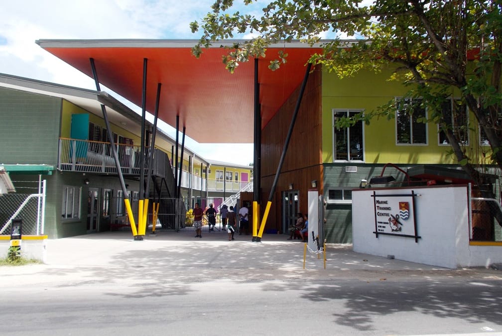
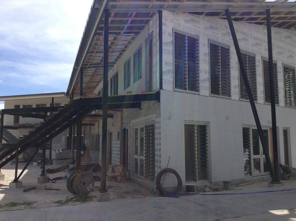
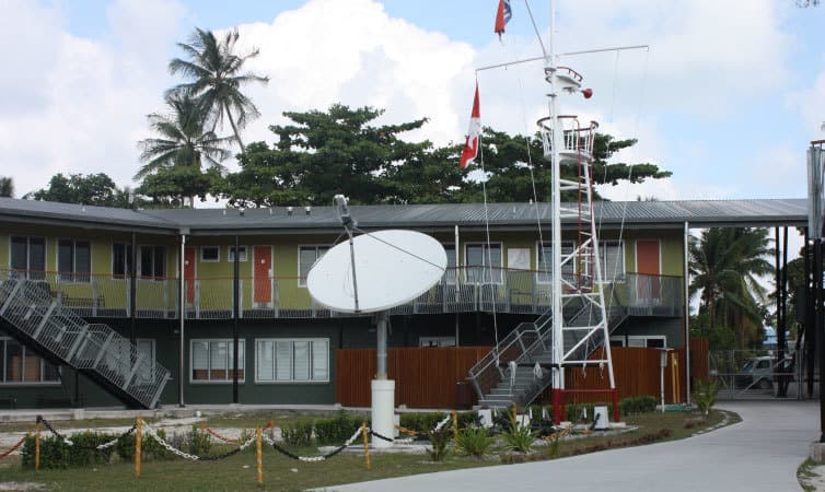
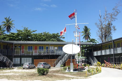
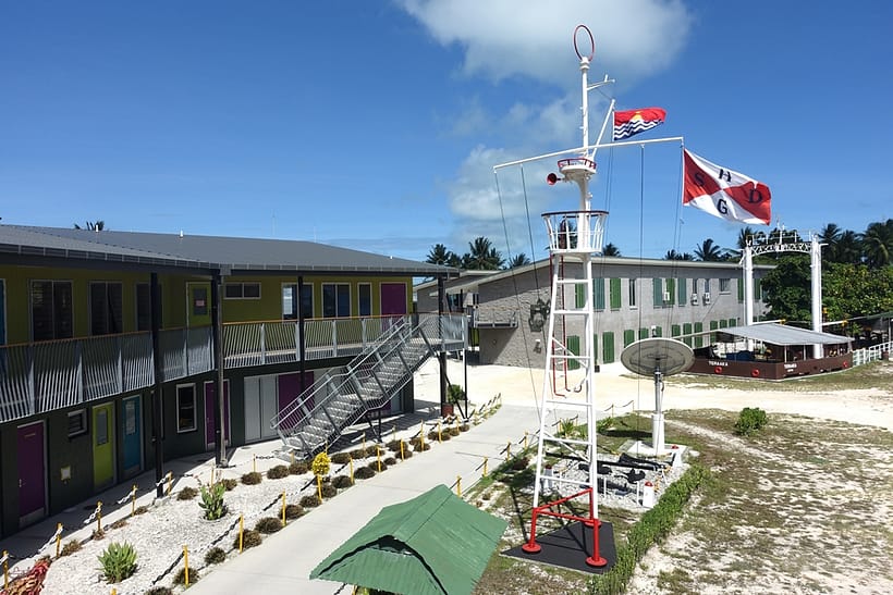
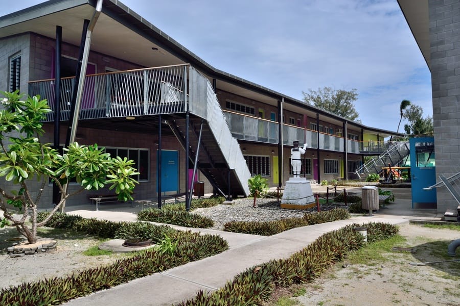
Location: Kiribati, Gilbert Islands, Pacific Ocean (circa. 2006) Design Brief: New Build Structure, Walkways, Stairs and Balustrades CAD System: StruCad
Quite often we are presented with projects on tight deadlines. This can be due to a variety of reasons, but how often is it because there is only one boat leaving and the next might not be for another three months or so?
This is how this project began with a two week turnaround for the metalworks and structure design package to be completed, including review and approval. It was with these criteria that I was presented and asked, ‘can we make it happen?’ The answer was, ‘yeah, but it’s gonna be tight!’.
So. No time to spare. Impossibly large package of work to complete. What could go wrong? The answer to that is, nothing. Nothing could go wrong, there was no room for that either.
My plan was to model the main structural components to form a project basis and split the work packages into two areas. Main Structure and everything else.
I got to work and completely modelled the structure without connections. This allowed us to have an accurate layout. Then I shared the model with my colleague where he continued with the structural connections and I continued with the walkways, stairs and balustrade details.
It was with this strategy that we were able to complete our design in time as well as having a fully coordinated package, all of this before multiuser space really took off.
I’ve found that when we are confronted with problems there is an opportunity to think outside the box to find solutions. It’s the mindset that helps drive a solutions based approach to my work.
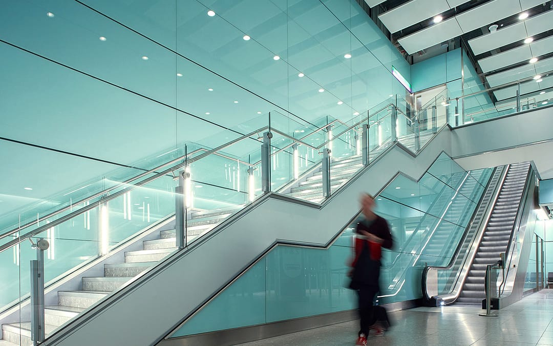
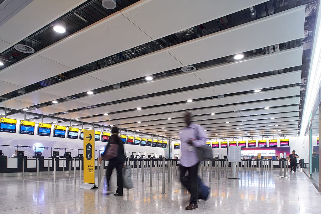
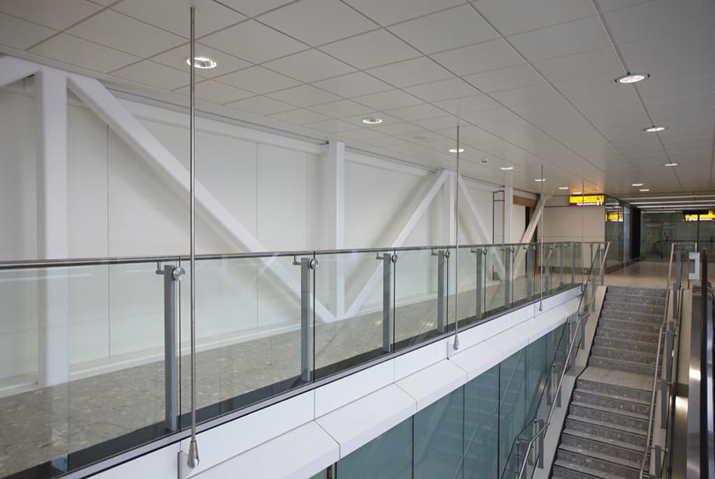
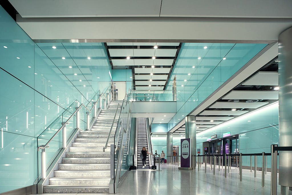
There are few places where your work will be viewed by tens of thousands on a day to day basis. Heathrow airport is one of those places. It was my absolute pleasure to be involved with this project.
During the revitalisation of T3 I was tasked with the production drawings for the Stair Structure and Glass Balustrade Systems. As well as the various support structures throughout the project. We were to incorporate the original 2-D parts details as utilised in T2 into the new details, so that the continuity of design would flow from one terminal to the next.
Whilst the part details would remain, there was still a lot of design required around the interfaces of existing elements such as the hanging supports for the retail sector which needed to fit around existing HVAC and main structure. The new stair structures and balustrades which needed to interface with the new escalators. Not to mention the glass partitions and monitor displays that were fitted to cambered beams, requiring adaptive mounts.
Overall this was a challenging project with a rewarding outcome.
We use cookies on our website to give you the most relevant experience by remembering your preferences and repeat visits. By clicking “Accept All”, you consent to the use of ALL the cookies. However, you may visit "Cookie Settings" to provide a controlled consent.
This website uses cookies to improve your experience while you navigate through the website. Out of these, the cookies that are categorized as necessary are stored on your browser as they are essential for the working of basic functionalities of the website. We also use third-party cookies that help us analyze and understand how you use this website. These cookies will be stored in your browser only with your consent. You also have the option to opt-out of these cookies. But opting out of some of these cookies may affect your browsing experience.
Necessary cookies are absolutely essential for the website to function properly. These cookies ensure basic functionalities and security features of the website, anonymously.
Cookie
Duration
Description
cookielawinfo-checkbox-analytics
11 months
This cookie is set by GDPR Cookie Consent plugin. The cookie is used to store the user consent for the cookies in the category "Analytics".
cookielawinfo-checkbox-functional
11 months
The cookie is set by GDPR cookie consent to record the user consent for the cookies in the category "Functional".
cookielawinfo-checkbox-necessary
11 months
This cookie is set by GDPR Cookie Consent plugin. The cookies is used to store the user consent for the cookies in the category "Necessary".
cookielawinfo-checkbox-others
11 months
This cookie is set by GDPR Cookie Consent plugin. The cookie is used to store the user consent for the cookies in the category "Other.
cookielawinfo-checkbox-performance
11 months
This cookie is set by GDPR Cookie Consent plugin. The cookie is used to store the user consent for the cookies in the category "Performance".
viewed_cookie_policy
11 months
The cookie is set by the GDPR Cookie Consent plugin and is used to store whether or not user has consented to the use of cookies. It does not store any personal data.
Functional cookies help to perform certain functionalities like sharing the content of the website on social media platforms, collect feedbacks, and other third-party features.
Performance cookies are used to understand and analyze the key performance indexes of the website which helps in delivering a better user experience for the visitors.
Analytical cookies are used to understand how visitors interact with the website. These cookies help provide information on metrics the number of visitors, bounce rate, traffic source, etc.
Advertisement cookies are used to provide visitors with relevant ads and marketing campaigns. These cookies track visitors across websites and collect information to provide customized ads.